Sun City G-Scale Railroad Crossing
A complete, Arduino-driven railroad crossing package: IR detection, alternating LEDs, dual servos, and a looping crossing bell sound — designed, documented, and taught as a live workshop for the Sun City model railroad club.
Project Snapshot
The goal: build a reliable, repeatable railroad crossing for a G-scale layout that felt like a real piece of infrastructure — and use it as the centerpiece for a hands-on class.
- Trigger: Infrared sensor watching the track.
- Effects: Alternating LEDs, two synchronized servos, and a crossing bell loop.
- Audience: Sun City model railroad club members, most new to Arduino.
- Deliverables: Working hardware, final sketch, wiring diagram, and printed guide.
This page is the portfolio view: the journey, design choices, and finished package. The full step-by-step teaching guide lives with the club materials in Sun City.
Role & Responsibilities
- Hardware design & prototyping (sensors, LEDs, servos, MP3).
- Arduino firmware: detection logic, timing, animation, and MP3 control.
- Wiring diagram & documentation for non-technical builders.
- Delivered live demo: laptop setup → code upload → crossing in action.
Exact Parts Used in the Final Build
This is the hardware that went into the final Sun City demo crossing — the exact stack that drove the IR detection, lights, gates, and sound.
Control & Sensing
- 1 × Arduino UNO R4 WiFi (5 V, main controller)
- 1 × IR sensor module (3-pin, digital output, active-LOW)
Indicators & Motion
- 4 × 5 mm red LEDs for the crossing signals
- 4 × 220 Ω resistors (LED current limiting)
- 2 × hobby servos for the crossing arms
Audio Path
- 1 × serial MP3 player module (microSD-based)
- 1 × microSD card with
001.mp3crossing bell sound - 1 × small 8 Ω speaker
- 1 × 1 kΩ resistor in series with Arduino TX → MP3 RX
Power & Prototyping
- 1 × solderless breadboard for the demo build
- Jumper wires (male–male and male–female)
- 5 V USB power for the Arduino
- Optional: separate 5 V rail for servos if using higher-torque motors
For the class handout, these parts were summarized into a printable list along with the wiring diagram so anyone could rebuild the crossing from scratch.
The Journey: From Idea to Workshop
The first requirement was simple on paper: “When the train goes by, make the lights flash and the gates go down.” In practice, it became a small systems project involving sensing, motion, sound, power, and a friendly tuning experience for the club.
- Proof of concept. Started with a hall (magnetic) sensor test just to prove out the idea of the Arduino reacting to the train.
- Settling on IR. Moved to an IR sensor for more stable detection on the actual track.
- Adding personality. LEDs began alternating, servos were tuned, and the crossing got a voice via a small serial MP3 module.
- Packaging for teaching. Locked down pin mapping, created a clean wiring diagram, and wrote a sketch with a few clearly-labeled constants so the class could safely “play.”
- Live day in Sun City. Installed the Arduino IDE on a fresh laptop, uploaded the final sketch in front of the group, and assembled hardware on new Arduino. Modified LED speed and gate timing and re-uploaded to see results.
What started as a simple toy crossing ended up as a small but complete embedded system with a story, documentation, and a room full of people watching it come to life.
Build & Demo Videos
These clips capture how the project evolved — from a bare proof-of-concept on the bench to a full G-scale crossing with sound on the layout.
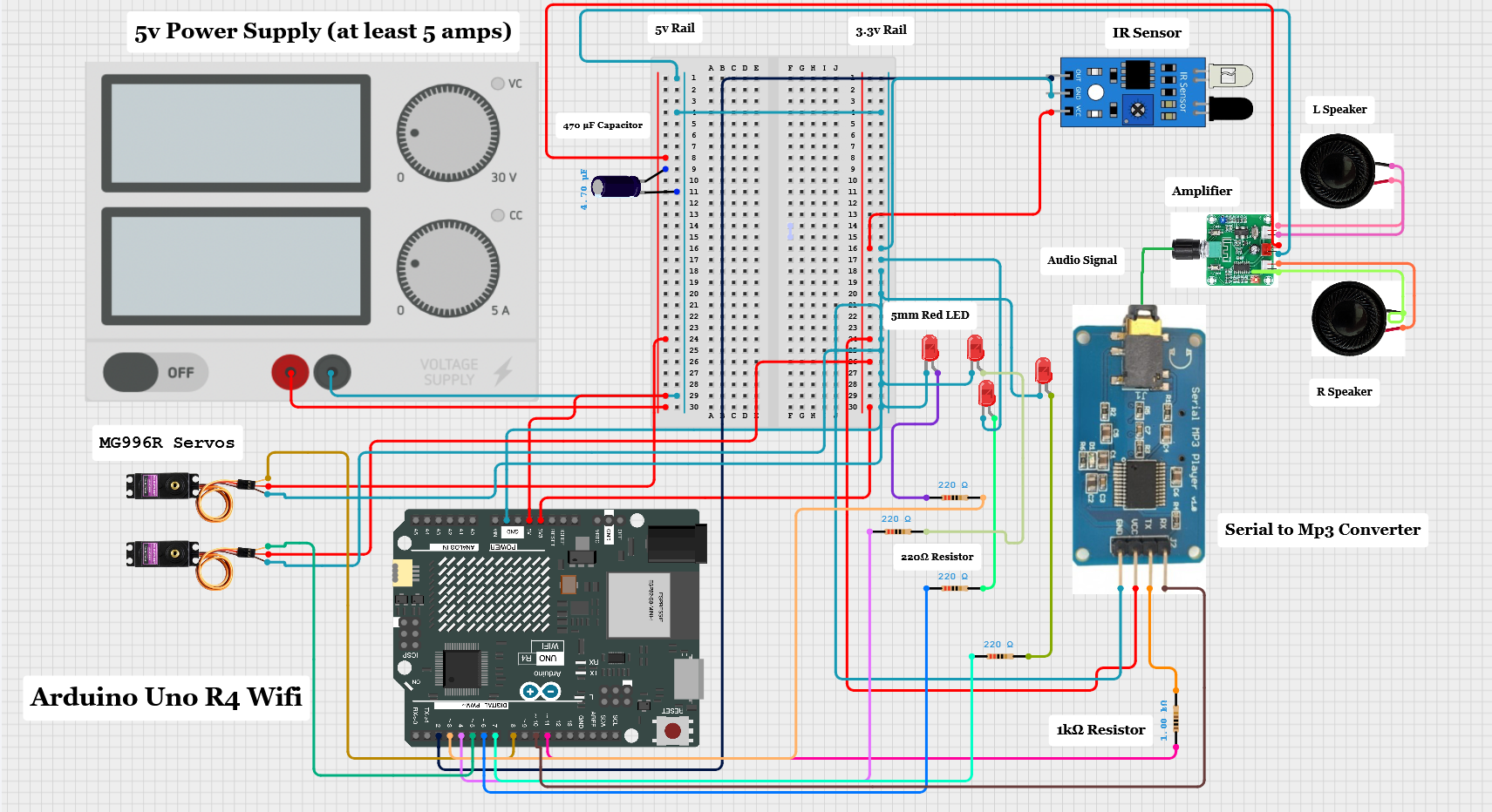
Wiring & Hardware Layout
The final wiring diagram became the core of the handout. It ties together the IR sensor on D2, LEDs and resistors on D3/D4 and D6/D7, servos on D5 and D8, and the serial MP3 board on D10/D11 with a 1 kΩ resistor on the Arduino TX line.
During the workshop, this diagram was projected and printed so builders could trace every connection without feeling lost in the jumper wire jungle.
Click the diagram to zoom in.
The Sketch — Final Version
The firmware is intentionally straightforward: a small state machine handling three phases (idle, active, returning up), plus a simple servo animator and a few MP3 helper functions. The class could safely experiment by changing only the constants at the top.
After the Workshop
The Sun City railroad crossing lives on as both a working feature on the layout and a teaching artifact. The hardware can be cloned from the wiring diagram, the sketch is classroom-friendly, and the project now serves as a jumping-off point for future additions: sensors on other tracks, ambient lighting, or even computer-controlled schedules.
For the club, it was a first dive into microcontrollers. For me, it was a chance to wrap hardware, firmware, documentation, and teaching into one package — and then watch a room full of people light up the first time the gates dropped on their own. The next step will be installing at the Red Poppy Railroad sometime early 2026.